Repairing the Eureka Mignon Brew Pro's Touchscreen
Updated 23. March 2025 (EEPROM contents)
Reflashing the Eureka Mignon Brew Pro’s Touchscreen Controller
Back in 2020, I bought a coffee grinder, the Eureka Mignon Brew Pro to be precise. I was quite happy with it until an issue with the touchscreen manifested itself about one year after I got the machine. After flipping the power switch, I could not adjust the grind timer using the “plus” button on the touchscreen. For more details on the problem, please refer to the next section. Since the machine was still within the warranty period, I contacted Eureka and the seller about my options. A couple of days later I got the new touchscreen by mail, and I swapped the defective one for the new one right away. The grinder worked again, I was happy, and I put the defective touchscreen in my parts drawer.
Fast forward to October of 2024: I encountered the same exact problem with the touchscreen again. This time, though, the grinder was already way outside the warranty period of two years. Nevertheless, I contacted the seller, and they offered a replacement touchscreen. For anyone wondering, the part number for the touchscreen assembly is 2312.0012v1904EU, and they run anywhere between 60 to 100 EUR online.
I really did not want to spend that amount of money on a spare part without trying to find out what was wrong with the touchscreen and maybe even repair it.
The Problem
To better understand the problem, first, some background information. The coffee grinder features two separate timers that can be set individually. Depending on how much coffee you want to grind, you either use the single or dual dose timer. After pressing the circular button on the front of the grinder, it starts grinding the beans while also counting down the timer. Once the timer reaches 0, the grinder automatically stops. After initially setting the correct timer for your grind size and type of beans, you only change the timer setting occasionally; for example, when switching to another bean type.
One day, after switching on the machine, I realized that I could not increase the timer setting in single dose mode using the “plus” button on the touchscreen. I was able to freely adjust the timer in double dose mode, but in single dose mode, the “plus” button was not working. Here is a video of the issue, courtesy of kaffee-netz.de.
I could still rely on the dual dose timer or the continuous mode for grinding coffee, but the single dose timer was not working anymore.
Collecting Information
After deciding to investigate the problem, I opened the grinder to remove the touchscreen assembly from the housing. A nice guide on how to remove the display can be found at here at Clive Coffee. I also picked up my other faulty touchscreen assembly. When looking at both touchscreens and comparing them, nothing stood out as obviously broken or defective. Everything looked good as far as I could tell. To tell both touchscreens apart easier, I will refer to them as A and B (A being the original one that came with the grinder and B being the replacement part I got in 2021).
Here is a look at the front and both backsides of the touchscreen assembly.
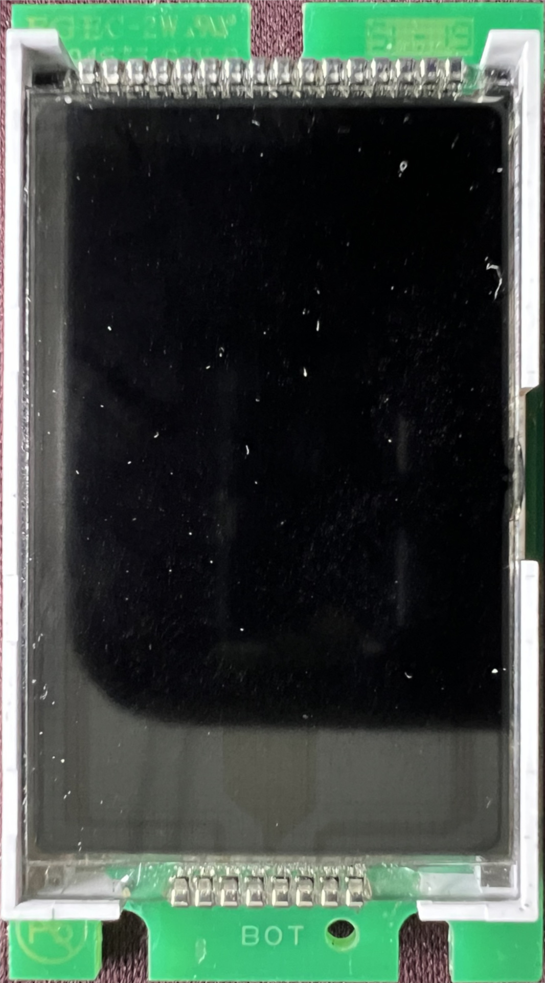
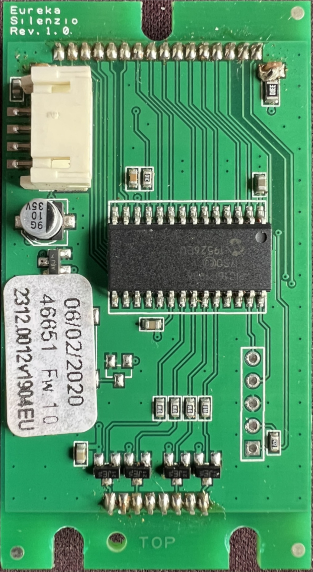
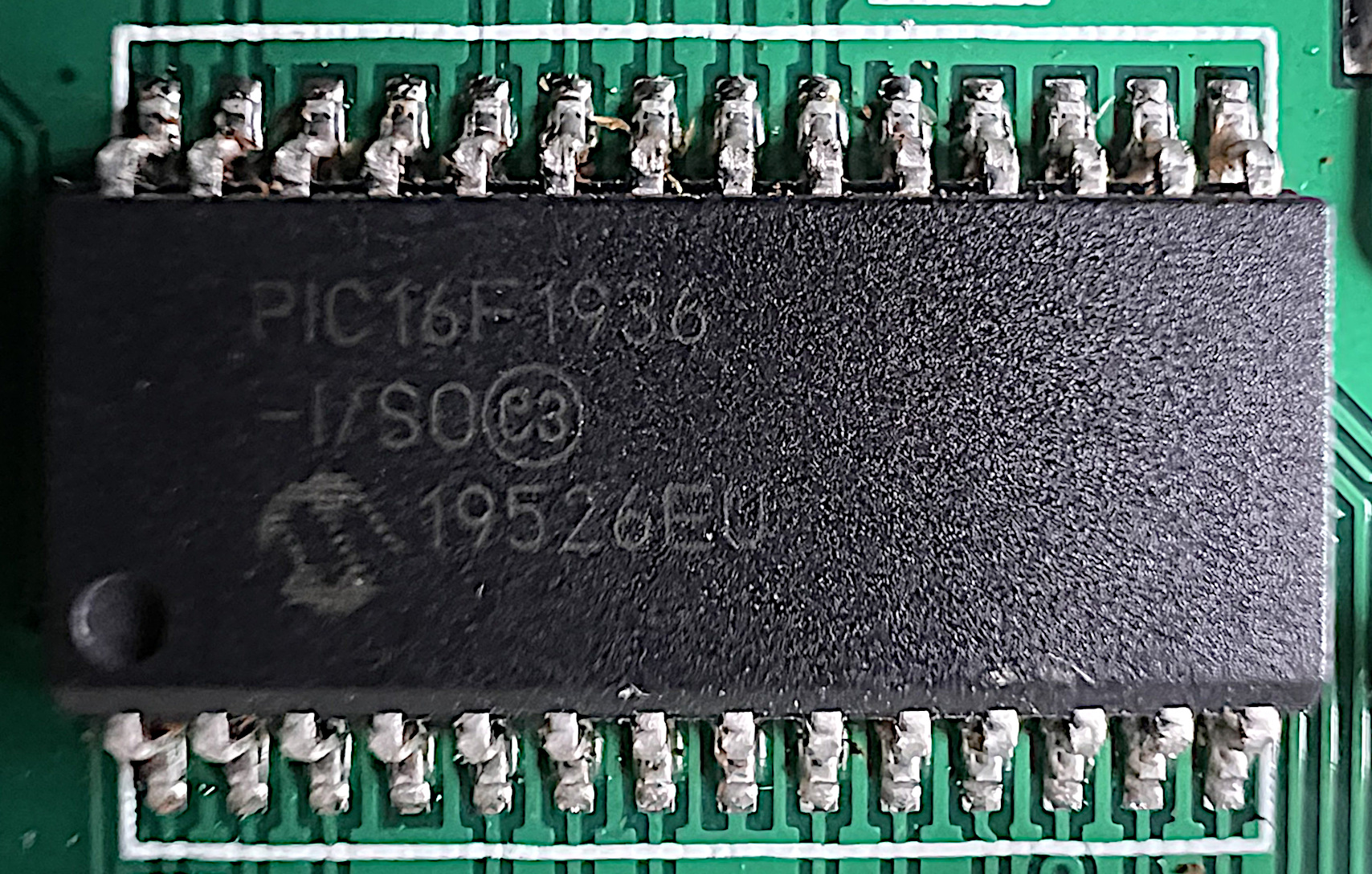
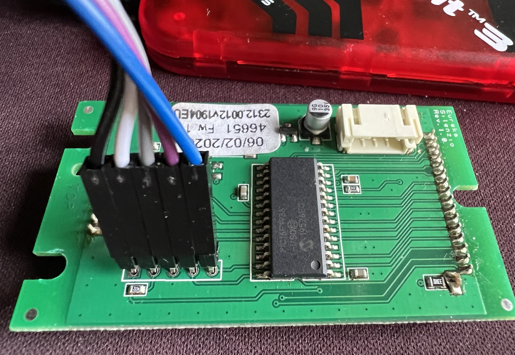
The actual touchscreen is mounted onto one side of the PCB, and the other holds the microcontroller among other things. The microcontroller thankfully has markings on it, and it is the exact same microcontroller for A and B. It is a PIC16F1936 made by Microchip, and the data sheet is available online. Here is what the microcontroller looks like up close:
Besides the microcontroller, both parts had a sticker on the backside of the PCB. The sticker for A reads:
06/02/2020
46651 Fw 1.0
2312.0012v1904EU
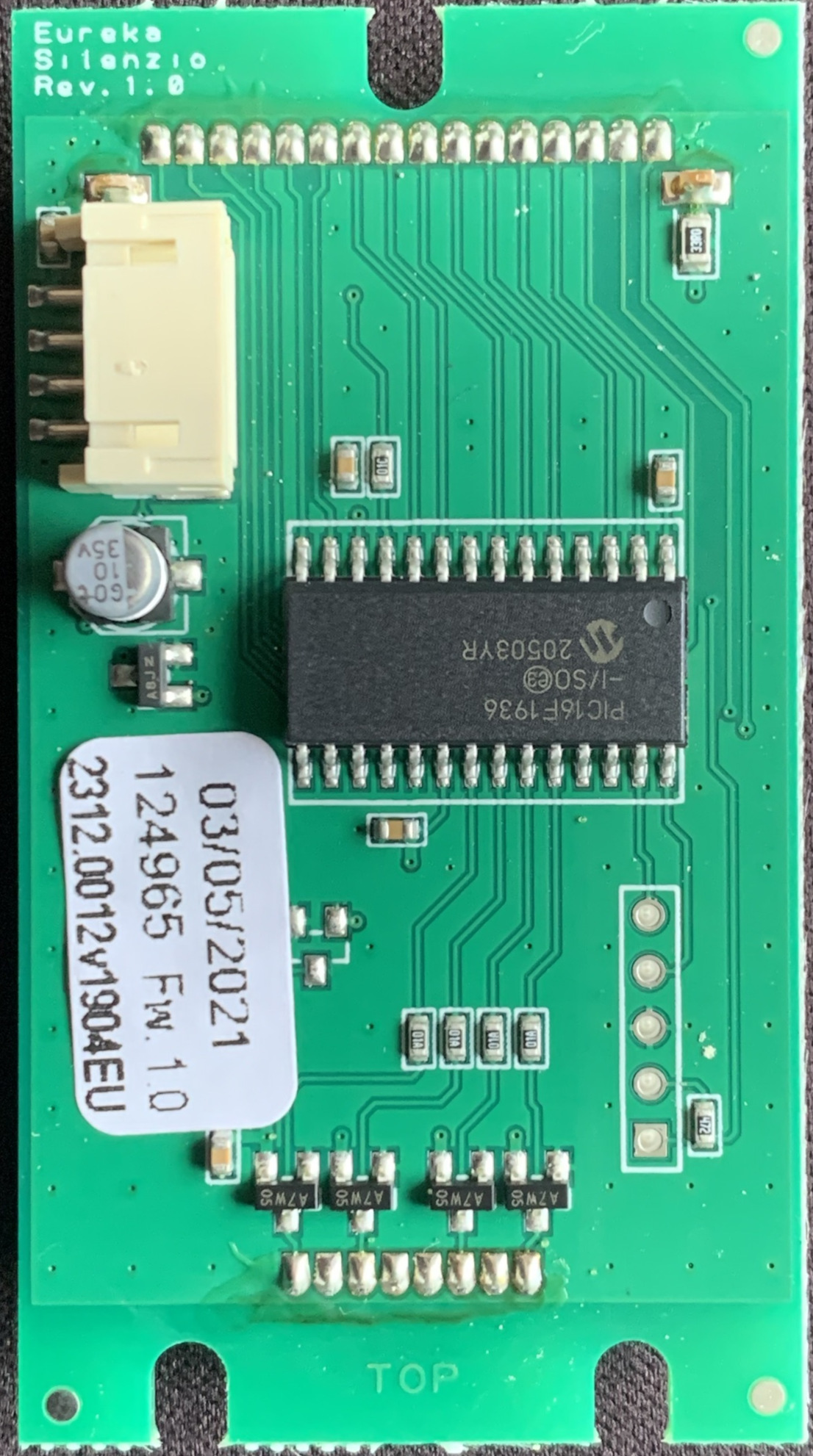
For B, the sticker reads:
03/05/2021
124965 Fw 1.0
2312.0012v1904EU
The strings 06/02/2020 and 03/05/2021 most likely represent the date of manufacturing.
I already knew 2312.0012v1904EU from the parts list.
It is the part number of the touchscreen assembly, and it is identical for A and B.
Also identical is the firmware version, likely denoted by Fw 1.0.
Both controllers appear to have been shipped with the exact same firmware version (we will come back to that).
The numbers in front of the firmware version (46651 and 124965) could indicate a production number of some sort.
I have no idea what these numbers represent.
I can only tell that the number on the newer part is higher.
All of this is speculation on my part, so take it with a grain of salt.
On the edge of the PCB, both parts have an identical marking reading:
Eureka
Silenzio
Rev. 1.0
This is probably referring to the hardware revision of the touchscreen assembly, and it seems that the PCB remained unchanged.
The last interesting part is an unpopulated header. This looks exactly like something where a programmer could be connected to the microcontroller, just minus the pins to easily attach jumper cables.
With no visible damage and with the suspicion that the problem was something software-related or microcontroller-related I decided to look into the PIC16F1936 in more detail. The plan looked like this:
- Try to extract the firmware from both touchscreen controllers to test if this is possible.
- Obtain the firmware from a brand-new touchscreen.
- Flash the brand-new firmware onto one of my old touchscreen controllers and see if that brings it back into working condition.
- Compare the firmware files and see what is different.
Setup
To read out the microcontroller, I had to make sure I had suitable equipment (hardware/software) and the necessary information.
Required Equipment
I never worked with a device from Microchip before, but it was quite easy to figure out what I needed to read out the PIC16F1936:
- PICkit3 (programmer used to connect to the microcontroller; I got a cheap v3 but there are newer versions around that probably work just as good)
- DuPont cable (5 wires, male-male)
- MPLAB IPE (Download)
Connecting to the PIC16F1936
With the equipment sorted out and ready to go, I turned to the pinout of the PICkit 3 and the PIC16F1936. Knowing which pin of the PICkit must be connected to which pin of the microcontroller is essential for reading the firmware. So, how do I connect my PICkit?
Pinout of the PICkit 3
The PICkit has a connector for 6 wires on the bottom of the housing. Fortunately, the data sheet for the PIC16F1936 does contain the pinout diagram for the PICkit. This is what it looks like (only 5 wires are connected, pin 6 is unused):
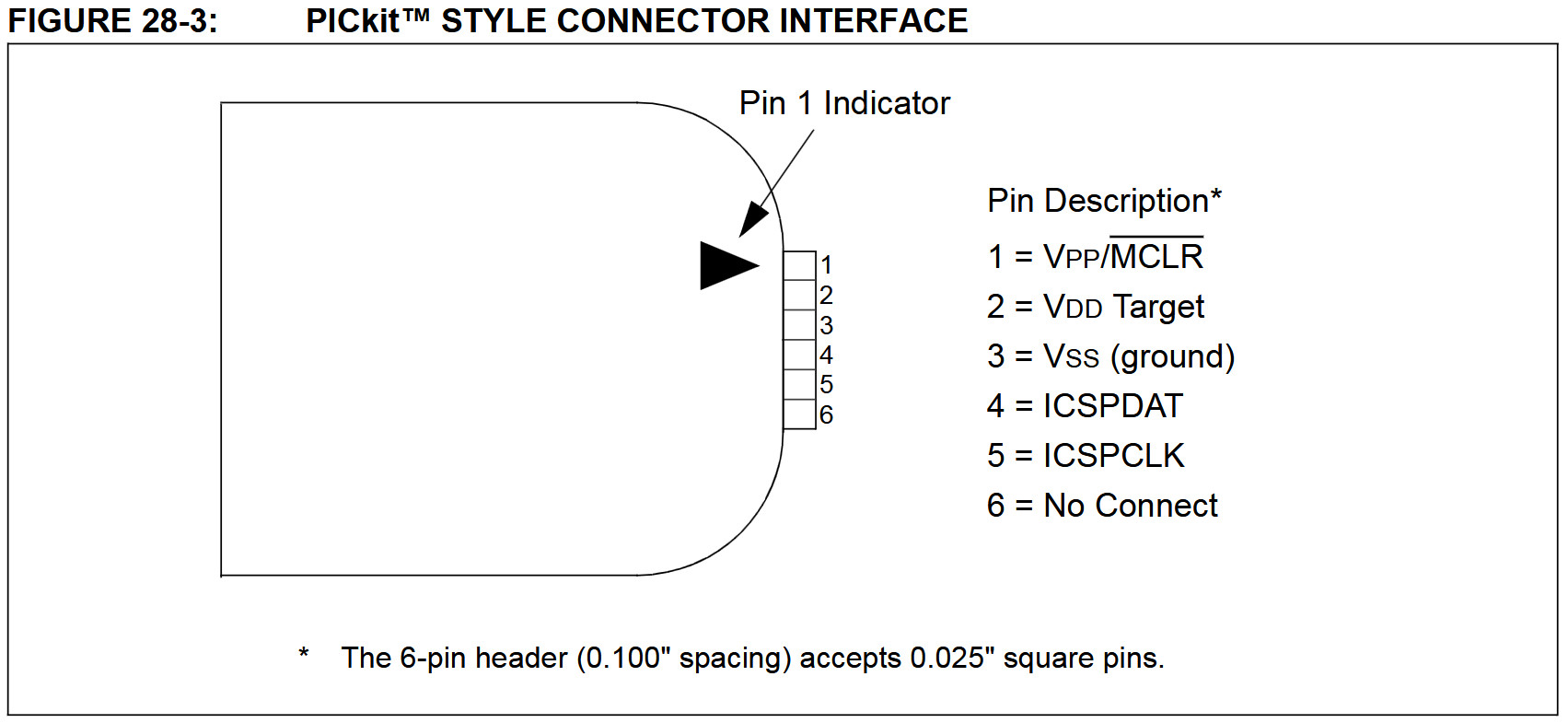
To connect the PICkit to a microcontroller, the following pins must be connected:
- MCLR/VPP
- VDD
- VSS
- ICSPDAT
- ICSPCLK
Pinout of the PIC16F1936
Next up is the microcontroller. To find out which pins need to be connected to the PICkit, the data sheet comes in handy, again. According to the data sheet, the pinout of the PIC16F1936 looks like this:
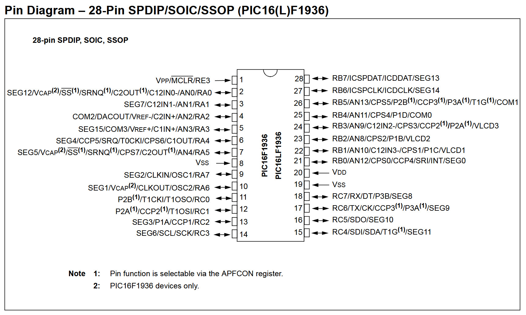
Chapter 28.0 of the data sheet lists the pins that must be connected to the PICkit for “ICSP programming” (I also added the pin number from the pinout diagram):
- ICSPCLK (pin 27)
- ICSPDAT (pin 28)
- MCLR/VPP (pin 1)
- VDD (pin 20)
- VSS (pin 19 or pin 8)
Connecting the Programmer
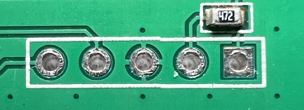
At this point I had learned that I needed to connect five pins of the microcontroller to the PICkit. One way to hook up the PICkit is to directly connect to the pins of the microcontroller. However, often there is an alternative (or more) that is far easier to use. Remember the five-pin-connector on the PCB? This one here?
Before trying to connect directly to the pins of the microcontroller using grabbers or something I decided to just try this promising looking connector. Spoiler: it worked.
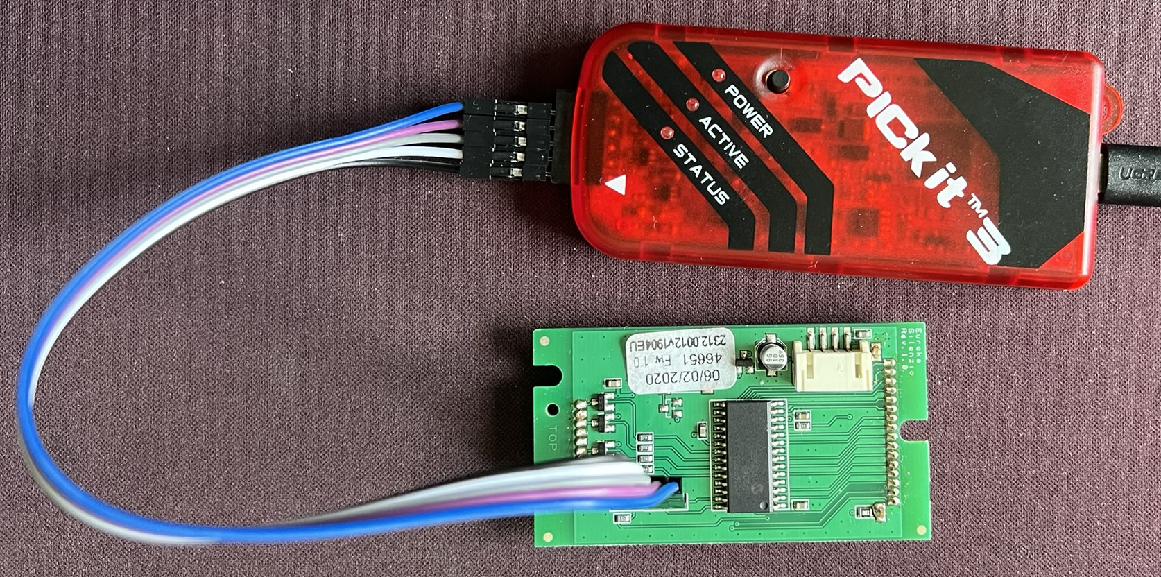
Here is the same connector with labels. It is exactly the same order as on the PICkit (see Pinout of the PICkit 3). Unfortunately, it is difficult to solder on some pins for a more stable connection. The display/touchscreen on the other side of the PCB is mounted very close to the PCB barely leaving any gap. However, the connection is good enough by just pressing the 5 wires into the connector.
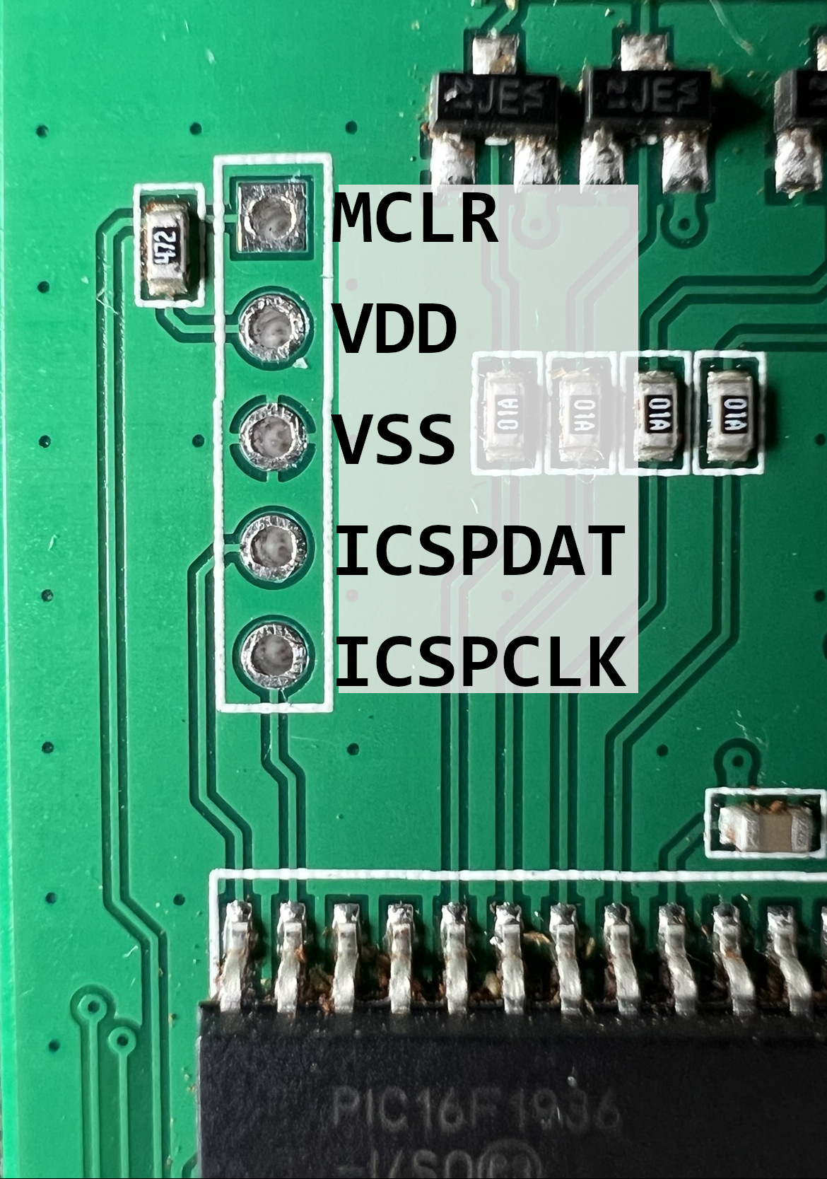
This is how it looked like after I connected the PICkit to the PCB:
Configuring MPLAB IPE
To read out and program the controller, I had to change a few settings in MPLAB IPE. Here is a list of all the settings that I adjusted:
- Set the device to “PIC16F1936”
- Check that the PICkit is selected under “tool”
- Go to “Settings” and activate the “Advanced Mode” (the default password is “microchip”)
- Go to “Production” and activate “Allow Export Hex”
- Go to “Power” and activate “Power target circuit board from PICkit”
Extracting the Firmware
With MPLAB IPE set up and the PICkit connected I finally tried reading out the firmware. After pressing the “Connect” button in MPLAB IPE the output pane looked like this:
MPLABComm USB Version: 3.48
MPLABComm Serial Access Version: N/A


*****************************************************

Connecting to MPLAB PICkit 3...

Currently loaded firmware on PICkit 3
Firmware Suite Version.....01.56.09
Firmware type..............Enhanced Midrange
Programmer to target power is enabled - VDD = 5.000000 volts.
Target device PIC16F1936 found.
Device Revision ID = 9
After establishing the connection, I went on to read out the firmware. For this I hit the appropriately named “Read” button. Here is what was added to the output pane, appended to what is already there:
Reading...

The following memory area(s) will be read:
program memory: start address = 0x0, end address = 0x1fff
configuration memory
EEData memory
User Id Memory
Read complete
After reading the firmware, I exported it to a hex file with an suitable name (e.g., “PIC16F1936-[ManufacturingDate]-faulty.hex).
File --> Export --> Hex
Please note that MPLAB IPE only allows exporting to hex files when the option is enabled in the “Advanced” settings. Refer to Configuring MPLAB IPE for details.
Exporting hex file...
Hex File successfully created at /home/user/temp/PIC16F1936-06022020-faulty.hex
Now I had everything contained in the microcontroller stored in a hex file as a backup:
- program memory
- configuration memory
- EEData memory
- User Id Memory
I also created a backup from my other touchscreen for comparison.
Exporting hex file...
Hex File successfully created at /home/user/temp/PIC16F1936-03052021-faulty.hex
Extracting the Firmware From Spare Parts
After getting the firmware from the faulty parts it was time to get the firmware from spare parts that were never used besides the tests that these parts run during manufacturing. I got myself access to two completely new touchscreens (mint condition as far as I can tell) and I extracted the firmware from them both. After getting the hex files, I had a collection of four hex files in total:
- PIC16F1936-03052021-Faulty.hex
- PIC16F1936-06022020-Faulty.hex
- PIC16F1936-1823-Vanilla.hex
- PIC16F1936-1923-Vanilla.hex
Interestingly, the spare parts had stickers on them with additional information. Here is a photo of one of the spare parts next to a faulty part.
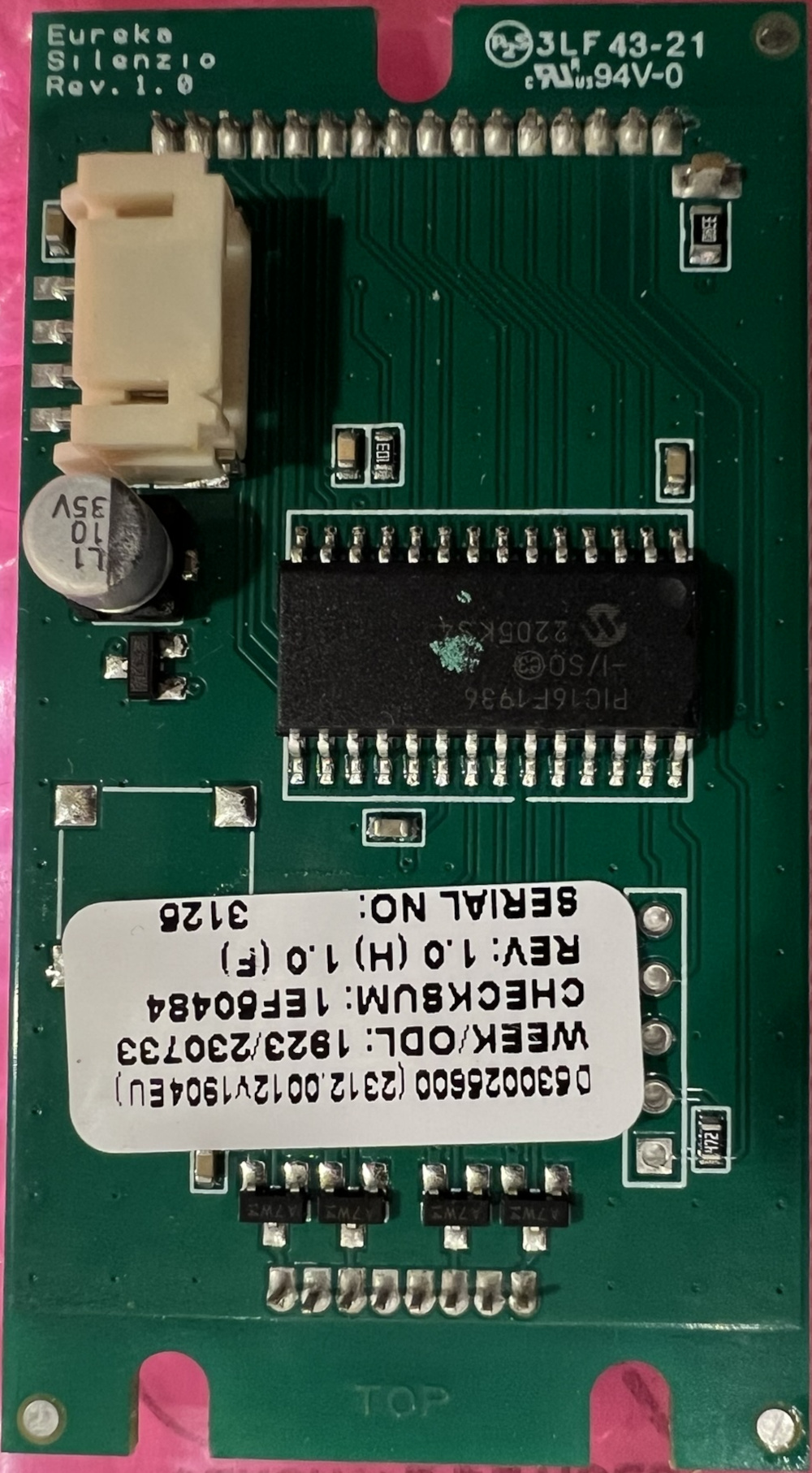
The color of the “new” PCB is a darker green and the sticker now holds more information. Besides that, the new part looks the same as the old parts.
0630026600 (2312.0012v1904EU)
WEEK/ODL: 1923/230733
CHECKSUM: 1EF50484
REV: 1.0 (H) 1.0 (F)
SERIAL NO: 3126
Flashing the Firmware
With the hex files from the spare parts available, it was time to see if I could flash my old display. I started MPLAB IPE and connected to the microcontroller just as I did when reading the firmware. After establishing the connection, I selected the correct hex file using the menu.
Loading code from /home/user/temp/PIC16F1936-1923-Vanilla.hex...
Approximate memory usage: 100%
2024-10-14 12:04:48 +0200 - Hex file loaded successfully.
Next, I clicked the “Program” button.
2024-10-14 12:05:26 +0200 - Programming...


Device Erased...

Programming...

The following memory area(s) will be programmed:
program memory: start address = 0x0, end address = 0x1fff
configuration memory
EEData memory
Programming/Verify complete
2024-10-14 12:05:41 +0200 - Programming complete
***   Hold In Reset mode is enabled   ***
After programming had finished, I hit the “Disconnect” button and removed the wires. I installed the display back into the grinder and switched it on. The first thing that caught my eye was the leading “0” on the display. This leading “0” would disappear when the problem of the non-functional “plus” button shows up. After pressing the “plus” button, the timer was adjusted accordingly. I also tried the dual dose timer and locking the setting (touch “plus” and “minus” buttons at the same time).
The touchscreen was working again. :)
Looking Into the Hex Files
Although I was happy that my touchscreen was working again, I wanted to have a look at the data in the hex files.
I took all four hex files and threw them into diff to find the changes between them.
Recap: The hex files were extracted from four different displays that were manufactured in 2020, 2021, and 2023 (2x).
All look the same with only minor differences, and they all have the same Fw 1.0 and Rev. 1.0 markings.
Diff of the Spare Part Hex Files
First, I looked at the two hex files from the brand-new spare parts:
diff PIC16F1936-1823-Vanilla.hex PIC16F1936-1923-Vanilla.hex
1029c1029
< :10E000003C0000006E000000010000000000000065
---
> :10E000003C0000006E000000020000000000000064
Only one byte in one line of the hex file has changed from 01 to 02 (and subsequently the checksum changed from 65 to 64).
Since only one byte has changed, it is safe to compare the two hex files from the faulty displays with only PIC16F1936-1923-Vanilla.hex.
Diff: Spare Part and Faulty Part A
Comparing the hex file from a spare part to the hex file from faulty part A:
diff PIC16F1936-1923-Vanilla.hex PIC16F1936-06022020-Faulty.hex
1028,1031c1028,1030
< :08000000FF3FFF3FFF3FFF3F00
< :10E000003C0000006E000000020000000000000064
< :10E0100000000000000000000000010000000000FF
< :10E0200000000000000000000000000000000000F0
---
> :10E00000E500FC00400000009C0000000100000052
> :10E010006B0000000000000006000200010000008C
> :10E02000400012000000000000000000000000009E
1060a1060
> :08000000FF3FFF3FFF3FFF3F00
More has changed than just one byte (as was the case with both “vanilla” hex files).
- Line 1028 in
PIC16F1936-1923-Vanilla.hex(:08000000FF3FFF3FFF3FFF3F00) has become line 1060 inPIC16F1936-06022020-Faulty.hex. The line was just moved to a different position. - Lines 1029-1031 were changed.
Diff: Spare Part and Faulty Part B
Comparing the hex file from a spare part to the hex file from faulty part B:
diff PIC16F1936-1923-Vanilla.hex PIC16F1936-03052021-Faulty.hex
1028,1031c1028,1030
< :08000000FF3FFF3FFF3FFF3F00
< :10E000003C0000006E000000020000000000000064
< :10E0100000000000000000000000010000000000FF
< :10E0200000000000000000000000000000000000F0
---
> :10E00000AF00FE003A00000099000C000000000084
> :10E010001000FF0000000000F600020001000000F8
> :10E02000C9000D000000000000000000000000001A
1060a1060
> :08000000FF3FFF3FFF3FFF3F00
This looks just like the comparison between PIC16F1936-1923-Vanilla.hex amd PIC16F1936-06022020-Faulty.hex.
Diff: Faulty Part A and Faulty Part B
Comparing the hex files from both faulty parts:
diff PIC16F1936-06022020-Faulty.hex PIC16F1936-03052021-Faulty.hex
1028,1030c1028,1030
< :10E00000E500FC00400000009C0000000100000052
< :10E010006B0000000000000006000200010000008C
< :10E02000400012000000000000000000000000009E
---
> :10E00000AF00FE003A00000099000C000000000084
> :10E010001000FF0000000000F600020001000000F8
> :10E02000C9000D000000000000000000000000001A
Analysis
After comparing the hex files with one another, it was obvious that there are only few differences between the faulty hex files and the ones from the working displays. To find out what data had changed, I decided to load a hex file into MPLAB X IDE and to use the different views (EE Data Memory, User ID Memory, etc.) to have a look on the data included in the hex file. I started the tool and imported PIC16F1936-1923-Vanilla.hex. Next, I opened the EE Data Memory view (aka the EEPROM contents):
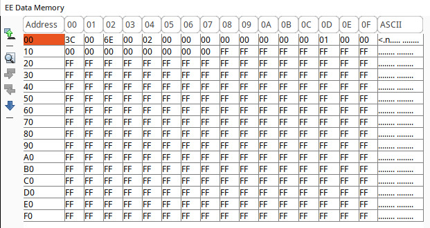
After looking at the output from my diffs and the EE Data Memory view, I recognized the values 3C and 6E.
Here is line 1029 from PIC16F1936-1923-Vanilla.hex: :10E000003C0000006E000000020000000000000064
It seems like a good fit for what I could see in the EE Data Memory view.
There were only a couple of 00 values too many.
A bit of searching online led me to this very helpful wiki entry from Segger.
EEPROM is mapped to 1E000: But the 256 bytes are stored as 16 bit values in the HEX file which doubles the areasize to 512 bytes. Fill bytes are stored as 0x00. Physically only 8 bits values are stored in the EEPROM!
I also looked up how exactly hex file records are constructed.
Microchip uses the Intel hex format and thankfully has some documentation on the format on their website.
These are the hex record fields for line 1029 from PIC16F1936-1923-Vanilla.hex:
: |
Start code (1 byte): Marks the beginning of each record |
10 |
Byte count (2 bytes): Number of data bytes in the record |
E000 |
Address (4 bytes): 16-bit address where the data should be loaded |
00 |
Record type (2 bytes): 00: Data record |
3C00 0000 6E00 0000 0200 0000 0000 0000 |
Data (variable length): Here 0x10 bytes as indicated by the byte count field. |
64 |
Checksum (2 bytes) |
When looking only at the data record field and removing the 0x00 padding as suggested by the Segger wiki, the data looks like this: 3C 00 6E 00 02 00 00 00.
These are the exact same values that are presented in the EE Data Memory view.
To be sure, I repeated the process for all three lines (1029-1031) of PIC16F1936-1923-Vanilla.hex (spaces added to make it easier to differentiate the hex record fields).
Original:
:10 E000 00 3C0000006E0000000200000000000000 64
:10 E010 00 00000000000000000000010000000000 FF
:10 E020 00 00000000000000000000000000000000 F0
Cleaned up:
3C 00 6E 00 02 00 00 00
00 00 00 00 00 01 00 00
00 00 00 00 00 00 00 00
Again, these are the exact same values that are presented in the EE Data Memory view. At this point it was safe to say that all the changes were happening in the EEPROM area of the PIC16F1936, specifically in the first 24 bytes of the 256 bytes EEPROM.
The only thing left at this point was this one line that switched places in the hex files.
In PIC16F1936-1923-Vanilla.hex it is located in line 1028 and in PIC16F1936-03052021-Faulty.hex it is located in line 1060.
Only the location has changed, the values all stayed the same.
Here is the hex record in question: :08000000FF3FFF3FFF3FFF3F00.
While looking at the other views available in MPLAB X IDE, the User ID Memory view looked very promising because it contained multiple instances of 0x3FFF.
I opened up the hex file and changed :08000000FF3FFF3FFF3FFF3F00 to :08000000FF3FFF3FFF2FFF3F10 using the checksum calculation method described here.
After the change, I looked at the User ID Memory view and I could see that the change indeed was in the User ID Memory area.
Here are the views for both the original and the modified hex record:
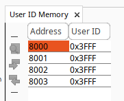

Chapter 4.4 of the PIC16F1936 data sheet contains more information on the purpose of the User ID Memory.
Four memory locations (8000h-8003h) are designated
as ID locations where the user can store checksum or
other code identification numbers.
Although I have no idea what these values represent, I had confirmation that the line that switched positions in the hex file was the User ID Memory area and since the values stayed the same, the difference in position can be ignored.
Findings
Based on my observations, it is probably safe to assume the following:
- The firmware has not been modified in any way over the course of about three years. The displays I used to read the hex files from were manufactured in 2020, 2021, and 2023. All the hex files from these displays are completely identical except for the first 24 bytes of the EEPROM. This means, that the actual program data must be the same for all four displays. Otherwise, there would have been more changed lines popping up when comparing the hex files.
- The values stored in the EEPROM are at least part of the problem. After overwriting the EEPROM with the data from the spare part, the machine was back in working condition. This means that somehow “problematic” values must have ended up in the EEPROM which then caused the problem that I had. How this happens, and when, I do not know. There could be a bug in the actual program running on the microcontroller that could lead to data corruption. There also could be other factors involved that are unknown to me.
EEPROM Contents
After being certain that I was looking at the EEPROM data, I took another look at the 24 bytes to see if I could identify some “known” values such as the timers.
Here is a table showing the first 24 byte of the EEPROM taken from PIC16F1936-1923-Vanilla.hex.
The only values I can currently make sense of are bytes 00 and 02.
⚠️ I updated the table below after haveing a closer look at the EEPROM values. The post can be found here.
| Byte | Value | Comment |
|---|---|---|
| 00 | 3C | Single dose timer lower byte |
| 01 | 00 | Single dose timer upper byte |
| 02 | 6E | Double dose timer lower byte |
| 03 | 00 | Double dose timer upper byte |
| 04 | 01 | Single dose counter 1st byte (lower) |
| 05 | 00 | Single dose counter 2nd byte |
| 06 | 00 | Single dose counter 3rd byte |
| 07 | 00 | Unknown |
| 08 | 00 | Double dose counter 1st byte (lower) |
| 09 | 00 | Double dose counter 2nd byte |
| 10 | 00 | Double dose counter 3rd byte |
| 11 | 00 | Unknown |
| 12 | 00 | Contrast setting |
| 13 | 01 | Last selected timer/mode (01 single, 02 double) |
| 14 | 00 | Continuous mode (00 disabled, 01 enabled) |
| 15 | 00 | Timer lock status (00 unlocked, 01 locked) |
| 16 | 00 | Unknown |
| 17 | 00 | Unknown |
| 18 | 00 | Unknown |
| 19 | 00 | Unknown |
| 20 | 00 | Unknown |
| 21 | 00 | Unknown |
| 22 | 00 | Unknown |
| 23 | 00 | Unknown |
Future Work
Since the difference between a working and a non-working touchscreen lies in the EEPROM, it makes sense to learn more about the structure and the contents of the EEPROM. So far, I only found the timer settings. However, at least the following values must be stored somewhere in EEPROM in addition to the two timer settings:
- Last used mode (single dose timer, dual dose timer, continuous mode)
- Timer locked/unlocked status
- Grind counter (6 digits per timer according to page 35 of the manual)
- Contrast setting for the display
Another interesting avenue would be to reverse engineer the firmware of the microcontroller to learn more about the inner workings and better understand how “problematic” data ends up in the EEPROM. A quick check already revealed that the symbols have been stripped. Reversing the firmware will likely be a more time-consuming task than reading and programming the PIC16F1936. :(
Other Eureka Grinders
I only have a Brew Pro available but according to the explosion diagrams of the other Mignon models (links in the links section), they all share the same display. Here is a list of all Mignon variants that use the 2312.0012v1904EU display part and where I could find an explosion diagram to confirm.
- Mignon Bravo
- Mignon Brew Pro
- Mignon Design
- Mignon Dolce Vita
- Mignon Perfetto
- Mignon Specialita
- Mignon Stark
- Mignon Turbo
- Mignon XL
At least one Mignon model uses a different display: the Mignon Libra. The Libra uses a display with the part number 2324.0012NLR00-XXX and this is probably due to the grind-by-weight system on that specific model. Since the Libra uses this display, it is highly likely that the Libra Brew also uses it. I did not find any documentation specifically for the Libra Brew, though.
Links
General Collection
- Eureka Mignon Brew Pro product page
- PIC16F1936 data sheet
- PICkit 3 in-iircuit debugger/programmer
- MPLAB Integrated Programming Environment (IPE)
- MPLAB X IDE download
- MPLAB IPE Intel HEX file format information
- Eureka Mignon user manual
- Eureka Mignon Specialita: Replacing the Screen and Control Panel
Explosion Diagrams